Aqua Computer V. 2 |
|||||||||||||||||||
|
This is my second attempt to build a computer that works when it is submerged into an aquarium. You can see my first serious attempt here. I am using the cable extensions from my last attempt, so the only expense is to the epoxy and lacquer used to seal the motherboard and graphics card. The hardware is as follows; Celeron 700 MHz, 128 MB PC133 ram, Diamond Viper 550 Graphics card with 16 MB ram, 2 GB hard disk drive and a Chaintech motherboard. |
|||||||||||||||||||
Software installation |
|||||||||||||||||||
|
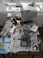
The first thing to do is to install the software. This way I can test the hardware during the process. Also it is not possible tom install software later, as there will be no floppy, optical drive or network connection in the computer. |
||||||||||||||||||
Original motherboard |
|||||||||||||||||||
|
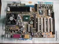
A picture of the motherboard and the memory module as they were before I started cutting. |
||||||||||||||||||
Graphics card |
|||||||||||||||||||
|
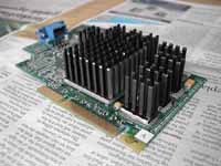
The graphics card with large heat sinks for passive cooling. The wok is shown here. |
||||||||||||||||||
Cooling of memory module |
|||||||||||||||||||
|
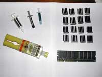
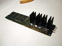
To avoid overheating of the memory module due to the insulating effect of the lacquer it is fitted with heat sinks. I donít have enough silver adhesive to all the heat sinks so I will be using regular cooling paste and glue the heat sinks to the memory module using epoxy. First cooling paste is applied to the memory module then the aluminum profile is placed on the memory module and epoxy is applied to the edge of the aluminum profile. There is a risk that the epoxy reacts with the printed circuit board causing it to fail. |
||||||||||||||||||
|
It may be overkill with the large aluminum profiles, but they are similar to the ones used on the graphics card and the chipset. To avoid the epoxy to harden before the profiles are mounted only four profiles are mounted at a time. They are glued at the short side at first and the later glued at the longer sides. |
||||||||||||||||||
|
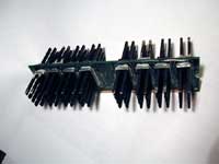
All the cooling profiles are mounted. It is almost overkill, but only ďalmostĒ. |
||||||||||||||||||
|
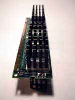
One last picture of the memory module |
||||||||||||||||||
Cooling |
|||||||||||||||||||
|
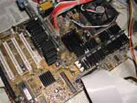
All the aluminum profiles have been mounted. Graphics card, memory, chipset (north and south bridge). |
||||||||||||||||||
Trimming the motherboard |
|||||||||||||||||||
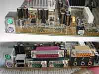
|
Everything on the motherboard poses a risk for failure. I will remove as much as possible to minimize the risk. The only connectors I need on the motherboard are mouse, keyboard and line-out. |
||||||||||||||||||
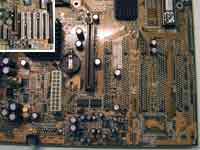
|
The motherboard after it is trimmed. ISA, PCI and AMR ports have been removed. |
||||||||||||||||||
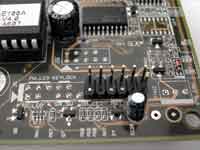
|
I only need the connector to turn of the computer, internal loudspeaker and hard disk drive activity LED. The rest of the connectors have been removed. |
||||||||||||||||||
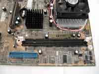
|
A single socket to the memory module is enough but there is not enough space to remove both the extra sockets without damaging the socked needed. |
||||||||||||||||||
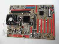
|
I have finished trimming the motherboard. The red squares marks areas where sockets and other stuff have been removed. The worst part of the trimming was trimming nearly 1600 metal pins on the back of the motherboard. |
||||||||||||||||||
Lacquering the hardware |
|||||||||||||||||||
|
With all the unnecessary things removed and the new heat sinks added it is time to seal the hardware with lacquer. Sealing the memory module and the graphics card were no problem. After the motherboard was given a few layers of lacquer it was time to seal the spare memory socket. However there are holes I the bottom of the sockets thus the lacquer came out the bottom and started to fill the socket that were going to be used. I mounted the memory module and hoped that the lacquer wound not prevent the memory module to work. To avoid that kind of error I mounted the graphics card and kept it on the motherboard for the rest of the time. |
|||||||||||||||||||
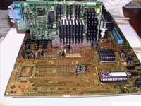
|
The motherboard after a few layers of lacquer has been applied. Many more layers are needed to make sure that all the components are protected by a watertight seal. |
||||||||||||||||||
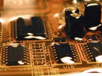
|
Motherboard after several layers of lacquer is applied. |
||||||||||||||||||
Test of hardware |
|||||||||||||||||||
|
After cutting all the unnecessary parts of the motherboard and sealing it with lacquer it is time to see if the computer still works. No need to continue working on it if the hardware I defect. It works fine as shown in this video clip: The clip is encoded using Xvid, the codec can be found on www.xvid.org. |
|||||||||||||||||||
Extending the ATX power cable |
|||||||||||||||||||
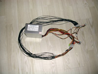
|
As I have no plan to submerge a 230V power supply into water I need to extend the 20 pins cable. A 20 cm extension cable has been modified by adding 1 meter cable. |
||||||||||||||||||
No casemod without some sort of light |
|||||||||||||||||||
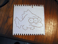
|
The perfect place to do an etch is inside the box to the hard disk drive. I think that the three eyed fish (Blinky) from The Simpsons is perfect for this casemod. |
||||||||||||||||||
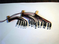
|
Better safe than sorry. To be sure the light is powerful enough I use 15 7200 mcd LEDís |
||||||||||||||||||
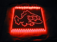
|
I had prepared the plate of acrylic to fit 30 LEDís, but 15 LED's is more than enough to give a bright light. |
||||||||||||||||||
|
I forgot to take pictures of the box to the hard disk drive. However it is just 6 pieces of acrylic glued with aquarium grade silicone. Four bolts are glued to the bottom. The bolts are used to mount the hard disk drive and the acrylic plate with the etching of Blinky. |
|||||||||||||||||||
The moment of truth |
|||||||||||||||||||
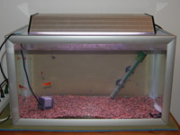
|
The aquarium with the fishes is ready. It is a 63 L tank with five guppies and 10 neon tetras. |
||||||||||||||||||
|
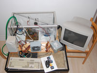
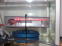
An 85 L aquarium with the computers is places on a lower table next to the 63 L tank. The power supply unit to the right is used to power the fan on the CPU heat sink. When the water level rises the fan is disconnected and the power supply unit is removed. The box with the hard disk drive is located to the right. The box is kept down with 2x2.5 kg weights. I am too lazy to extend the cables to the internal speaker and the power switch. The switch and speaker is kept above the water with a aluminum rod and cable ties. |
||||||||||||||||||
|
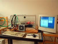
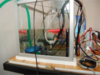
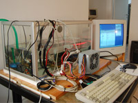
A few pictures of the setup as water are added. |
||||||||||||||||||
|
|||||||||||||||||||
|
|||||||||||||||||||
|
|||||||||||||||||||
The Computer is dead |
|||||||||||||||||||
|
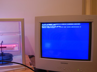
As expected the computer did not run perfectly for many hours.
|
|||||||||||||||||||
|
The BSOD showed the following error: STOP: 0x00000077 KERNEL_STACK_INPAGE_ERROR |
||||||||||||||||||
|
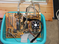
The cable extensions have been cut and the hardware is ready to be recycled. |
||||||||||||||||||
|
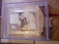
The box for the hard disk drive was not 100% waterproof. However this was not a big problem as the hard disk drive was mounted a little above the floor in the box. The hard disk drive has been tested in another computer and it works fine. |
||||||||||||||||||
Back to top of page |
|||||||||||||||||||


